Modular external fixation
1. Principles
Modular external fixator
The modular external fixator is optimal for temporary use. It is rapidly applied without need for intraoperative x-rays and can be adjusted later.
The frame of a modular external fixator consists of two partial frames (a, b), one on each main fracture fragment. Each partial frame consists of two pins in a bone fragment, connected with a rod. The two frames are joined with a rod-to-rod construction/connecting rod (c).
This construct allows manipulation and reduction of the fracture after pin placement and guarantees sufficient stiffness of the frame. It also allows pins to be inserted through safe zones, avoiding traumatized soft tissues.
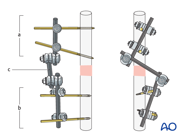
Optimal frame construction
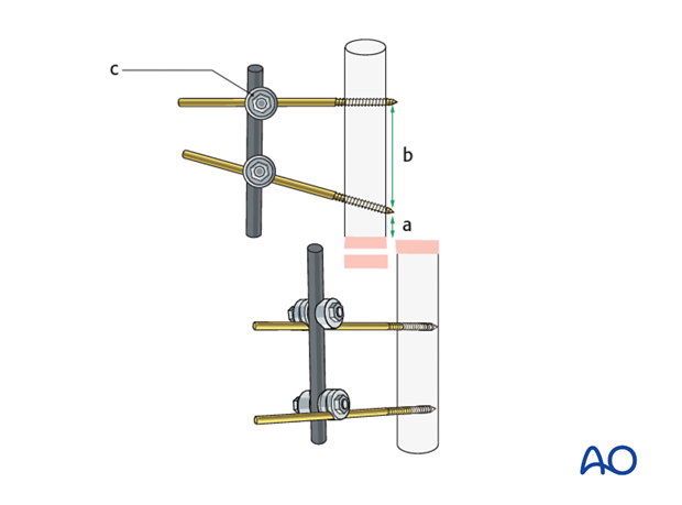
For the construction of the frame consider the following points:
- Pins are placed near the fracture site, but not too close to it, and so they avoid traumatized soft tissue (a)
- Pins are placed so that they are widely separated in each main fracture fragment (b)
- Rods are connected to the pins with rod-to-pin clamps (c)
- The rod-to-pin clamps are fully tightened so that each main fragment has its own partial frame
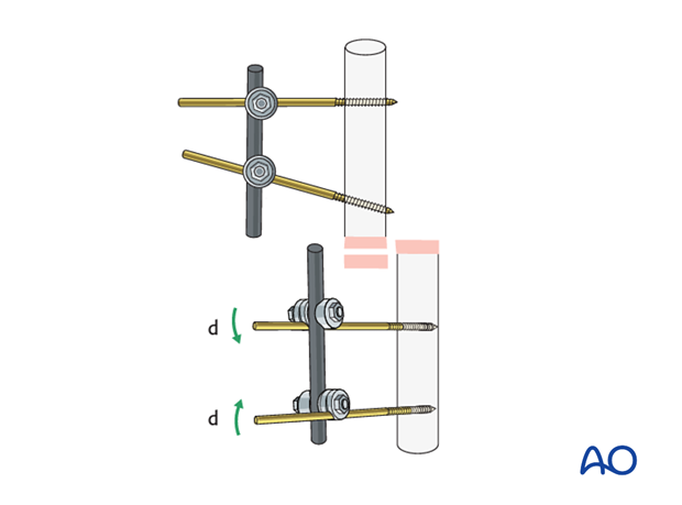
Pins can be ‘preloaded’ to improve their purchase in bone and to reduce the tendency to loosen over time. This can be achieved by either (1) the design of the pin, or (2) by how the pin(s) is/are implanted.
Achieving preload through pin design: a tapered pin in which the largest (proximal) diameter is slightly greater than the drill hole through which it is introduced will induce radial preload in the near cortex of the bone into which it is implanted. Inducing too much radial preload (caused by introducing a screw that is too large for the predrilled cortical bone) may cause (1) local bone microfractures or (2) bone ischaemia. Both may lead to necrosis and early loosening so this should be avoided.
Achieving preload through optimizing pin implantation: reduction in the risk of loosening of standard pins after implantation may be achieved by tensioning adjacent pins towards or away from each other. The load produced in the pin by the resistance of the pin to bending produces an asymmetrical load in the near cortical pin hole. If adjacent pin holes experience opposing loads then each pin neutralizes the tendency of the adjacent pin to loosen.
Further information on this topic can be found here:
Hyldahl C, Pearson S, Tepic S, et al. Induction and prevention of pin loosening in external fixation: an in vivo study on sheep tibiae. J Orthop Trauma. 1991;5(4):485-92.
The two partial frames are interconnected using a connecting rod.
The clamps are first provisionally tightened with a T-handle and then fully tightened using a wrench.
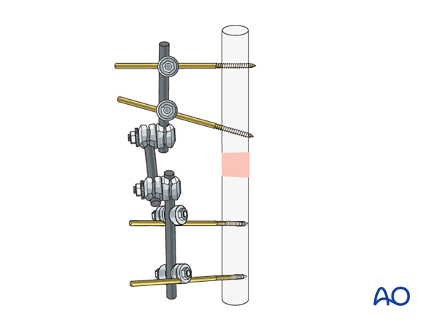
The stiffness of the frame may be increased by the following options:
- Using thicker pins
- Positioning the rod closer to the bone
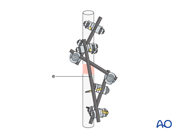
- Adding a second connecting rod (neutralization rod) (e) between the partial frames
- Placing more pins in each segment
These 3D models show the biomechanical behavior of the construct. Increasing the distance from the rod to the bone decreases the stiffness of the frame of the external fixation system. Therefore, the strain at the rod and the pin (especially the outer pin) is increased.
Compressive stress is shown in red and tensile stress is shown in blue in this animation.
These 3D models show that by adding a third pin, the strain concentration at each pin is slightly reduced. The whole construct provides increased stiffness, especially in torsion.
Equipment needed
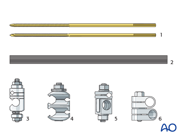
For the construction of the frame the following components may be used (shown for the large external fixator):
- Threaded pins (Schanz type pins, standard or self-drilling/self-tapping with radial preload; 5 or 6 mm)
- Carbon fiber rods or metal tubes (diameter of 11 mm)
- Rod-to-pin clamps (titanium, MRI safe)
- Combination clamps (rod-to-rod or rod-to-pin, self-holding, titanium, MRI safe)
- Rod-to-pin clamps (old type, still in use)
- Rod-to-rod clamps (old type, still in use)
Depending on the anatomic region, the large, medium, small, or mini external fixation system will be more appropriate. The pins, rods and clamps are similar in all systems, but vary in dimensions. For the application of special frames, further components may be needed.
2. Pin insertion
Pin placement
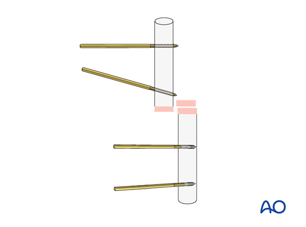
Two pins should be inserted in the safe zones in each of the proximal and distal fragments.
The risk of tendon penetration or injuries to nerves, vessels, and muscles is determined by the anatomy of each region. Pins should not be placed where they will enter a joint cavity.
When possible, the use of an image intensifier is recommended to facilitate optimal and safe pin placement.
In temporary external fixation, the pins should be placed so they do not interfere with planned later definitive fixation.
Skin incision
The position of each skin incision is determined by the pin position. As the fracture is reduced, the pin may move in relation to the skin, and the incision may then need to be extended in order to release any tension in the skin. If possible, this should be anticipated and the initial skin incision adjusted accordingly.
Predrilling
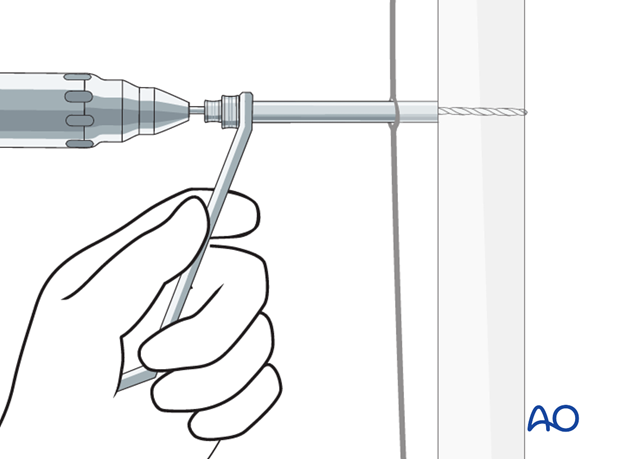
Unless self-drilling pins are to be used it is essential to predrill both cortices prior to the insertion of threaded pins.
Place a drill sleeve with trocar through the prepared soft-tissue channel to prevent damage to soft tissues and confirm correct positioning. The use of an image intensifier may be beneficial to determine correct pin trajectories.
Drilling through cortical bone should be performed under cooling to prevent heat formation followed by bone necrosis.
Pin insertion (conventional threaded pins)
Insert conventional pins by hand using the corresponding drill sleeve.
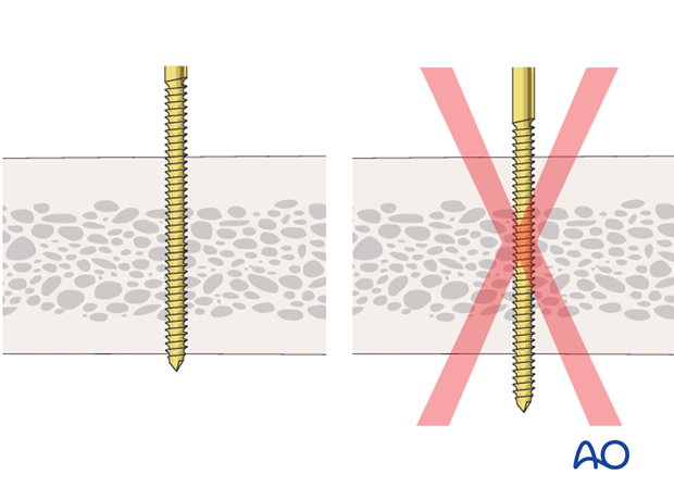
Ensure that both cortices are engaged; feeling the pin thread itself into the opposite cortex confirms correct insertion depth.
After the insertion of all pins, image intensification control in two planes is recommended.
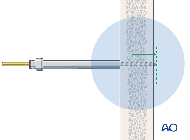
Conventional threaded pins should be bicortical so that the thread of the pin is fully threaded in the predrilled hole of the far cortex. The pins must not protrude too far since this would endanger the soft tissues.
Pin insertion (self-drilling Schanz screws)
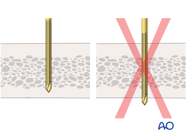
Insert each pin through the drill sleeve. A power tool is used to insert the screw through the near cortex. Once the screw reaches the far cortex, which can be felt easily, turn the pin manually for another one or two rotations to anchor the tip of the screw in the inner side of the far cortex.
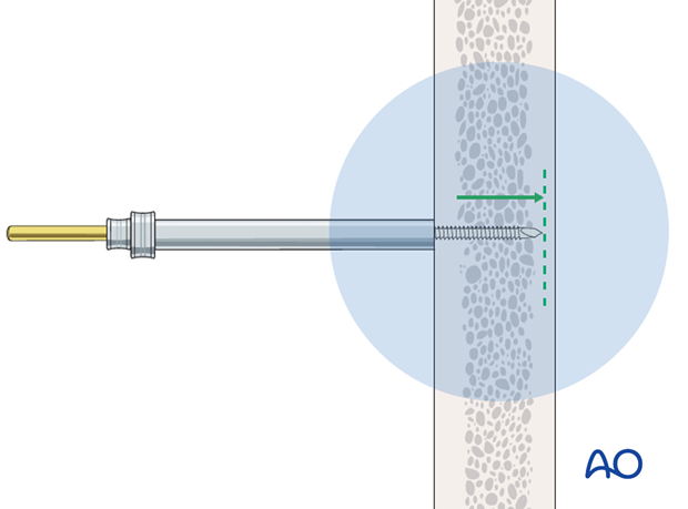
Self-drilling and self-tapping pins must not perforate the far cortex (the protruding sharp tip can cause soft-tissue injury if it projects beyond the cortex).
3. Frame construction
Frame assembly
Connect the two pins in each main fragment to a rod using rod-to-pin clamps.
The rod should lie close to the bone and the skin, but not so close as to risk pressure on the skin if the limb subsequently swells. There should be enough room between the rod and skin to allow cleaning.
Fully tighten the rod-to-pin clamps to complete the two partial frames.
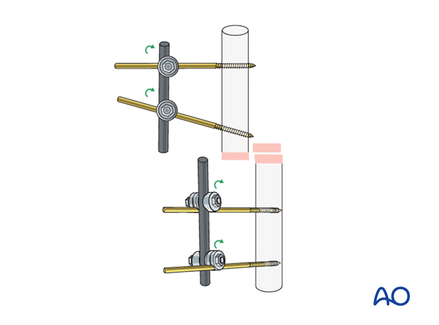
Connect the two partial frames with a rod using rod-to-rod clamps applied loosely enough to allow reduction of the fracture.
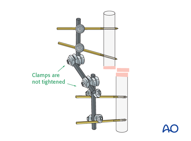
Pitfall: conflicting rods
4. Reduction and fixation
Reduction
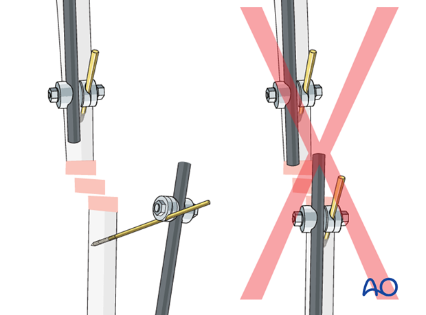
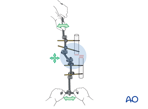
Using the partial frames as handles, manually reduce the fracture to obtain appropriate length, alignment, and rotation.
Check the provisional reduction in AP and lateral image intensifier views.
Fixation
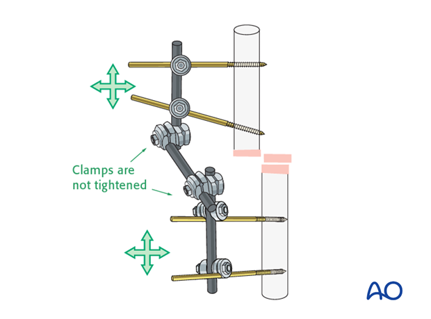
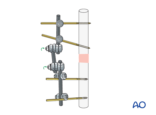
When satisfactory reduction has been obtained, tighten the rod-to-rod clamps to finalize the frame construction. Reconfirm reduction using image intensification.
If additional stability is needed to secure the reduction, attach an additional rod (neutralization rod) to the two partial frames. This may be attached at each end to either a rod or a pin.
If needed, a curved rod or two connected rods may be used.
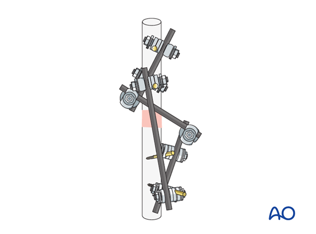
The lower 3D model shows an additional rod (neutralization rod) applied to a modular external fixation frame. This increases the stiffness and the stability of the construct. It adds rotational stability in particular and increases the bending strength, thus significantly reducing strains at the connecting rod.
Periarticular injuries
When the fracture lies close to a joint it may be more practical to stabilize small periarticular fragments with a joint-spanning frame.
This should generally be converted to a form of fixation which allows the joint to move as soon as is practical, otherwise there is a risk of long-term stiffness.
Associated fractures
In a limb with fractures at more than one site, for example ipsilateral femoral and tibial fractures, where both fractures are treated with an external fixator, it may be helpful to join the two frames.
Inspection and treatment of skin incisions
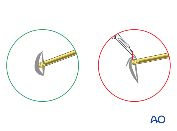
After the operation, stab incisions should be left open and treated locally with antiseptic dressings. Closing stab incisions prevents wound drainage, which increases the risk of pin track infection.
If there is tension on one side, the incision should be extended. If significant extension is required and the total incision becomes unnecessarily long the redundant portion of the incision may be closed.
5. Subsequent management after external fixation as temporary fixation
If external fixation was used because the patient was not fit to undergo definitive internal fixation, once the general condition has improved, definitive fixation may be considered.
Soft tissue healed
If the soft-tissue injuries have healed satisfactorily without pin track infection, the external fixation can safely be removed and replaced by internal fixation if the pin sites are clean.
Soft-tissue problems persist
If there is pin track infection, changing to a definitive internal fixation could lead to infection.
If the soft-tissue problems persist and/or the external fixator has been left on for two weeks or longer, or there are pin-track infections, the following steps should be taken:
- Remove the external fixator
- Debride the pin sites in the operating theater, using curettage and irrigation, taking specimens for microbiological study
- Temporarily stabilize in a splint or cast or place a new external fixator at new pin sites
- Let the pin tracks heal
- Proceed with internal fixation, covering with antibiotics, as necessary, and as determined by any positive microbiological cultures
Pitfall: intramedullary infection
6. External fixation as definitive fixation
Indications
In the event that soft-tissue healing is not satisfactory after four to six weeks, and there is no pin-track infection, the external fixator can be left on until the fracture has healed.
In non-compliant patients the external fixator is often indicated as the first and final treatment.
In children, fracture healing is often complete in six to eight weeks. If external fixation is initially chosen, it should remain until the fracture has healed.
Adjusting the fixator
If a temporary fixator was initially rapidly applied when the patient was severely injured, it may be necessary to adjust the fixator to obtain an appropriate reduction and provide additional stability once the decision has been made to continue external fixation as the definitive treatment. In some cases, a new construct may be better able to maintain satisfactory reduction until the fracture has healed.
Optimal stiffness
A small amount of movement between the fracture fragments will stimulate callus formation. In highly fragmented fractures, movement is spread over the entire fracture area, but in simple, two-part fractures all movement occurs at only one fracture site.
Inadequate stability will delay fracture healing. However, beware of too much stiffness or rigidity, as this may also delay healing, especially in open fractures.
Pitfall: pin loosening or pin-track infection
• Remove all involved pins and place new pins in a healthy location
• Debride the pin sites in the operating theater, using curettage and irrigation
• Take specimens for a microbiological study to guide appropriate antibiotic treatment complementing the surgical debridement


