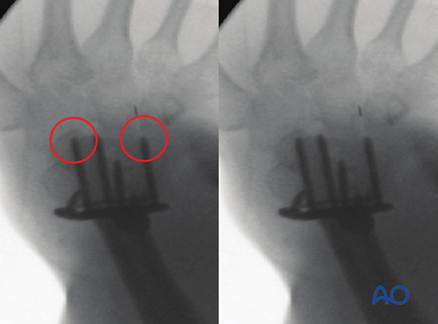
Intraoperative imaging of the distal forearm
1. Introduction
Fluoroscopic visualization of anatomical fracture reduction and correct implant placement for the distal forearm can be significantly facilitated using the following views:
- AP and lateral views of the distal forearm (including tangential views)
- Oblique views (supination and pronation)
- Dorsal views (dorsal tangential and skyline views)
The following represents ideal imaging with the patient in the supine position with the arm resting on an arm table. The wrist is adjusted in different positions to acquire the respective views.
The C-arm is usually oriented vertically. Only dorsal views need some adjustments.
2. AP view of the distal forearm (incl tangential views)
Positioning for optimal view
- The forearm is in full supination or full pronation
- The beam is placed vertically
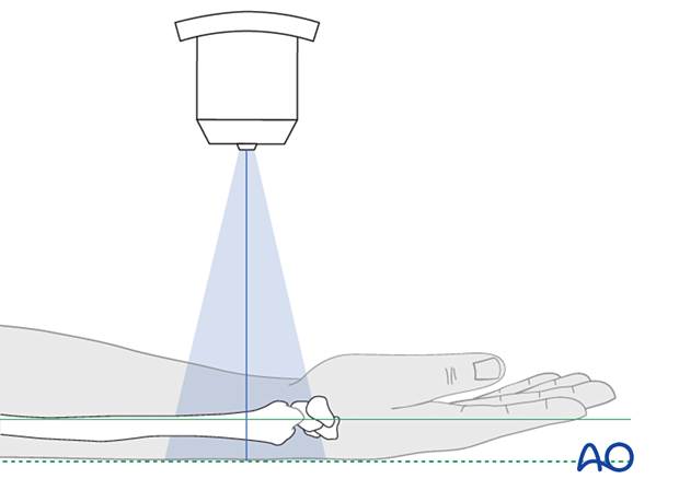
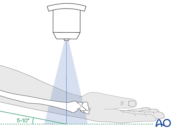
AP tangential view
Use additional tangential views to clear the radiocarpal joint space. The radiocarpal joint space is slightly tilted by 5°–10°.
In full supination, the elbow should be lifted by this degree. Alternatively, the C-arm may be adjusted.
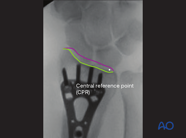
Anatomical landmarks and lines
The following lines and landmarks can be observed:
- Proximal carpal row (scaphoid, lunate, and triquetrum)
- Distal radioulnar joint (DRUJ)
- Dorsal rim
- Palmar rim
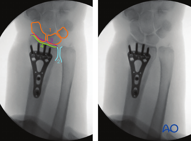
Central reference point (CRP)
Verification of optimal view
The optimal view is obtained when the image is centered over the DRUJ. The joint space of the DRUJ is then usually visible.
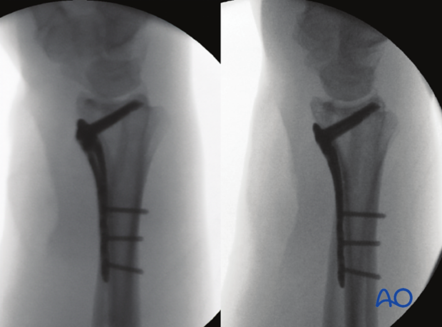
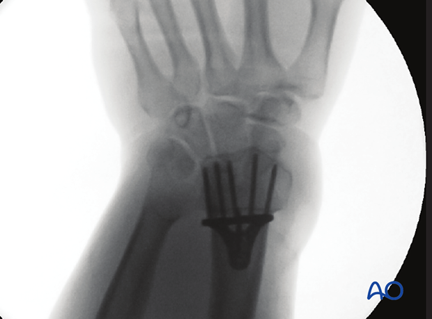
Correct intraoperative AP view
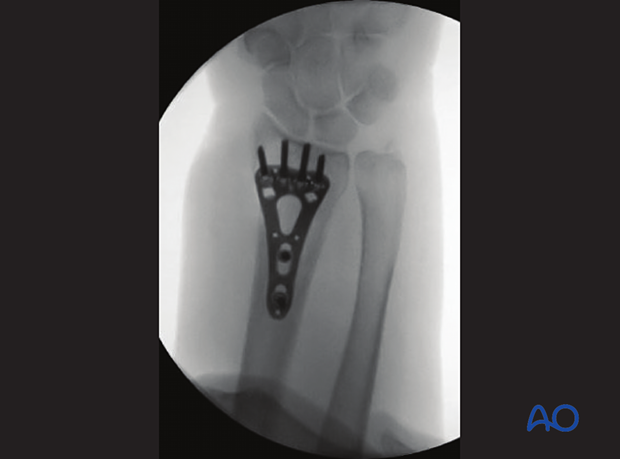
Left image: Incorrect intraoperative view, not centered on DRUJ
Right image: Postoperative view, same patient, centered on DRUJ, revealing malposition of the implant
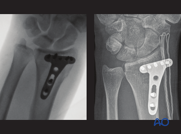
What can be observed
This view is particularly useful for identifying:
- Böhler’s angles
- Radiocarpal joint and DRUJ congruency
- Correct plate position
- Rule out screw penetration into the radiocarpal joint or the DRUJ
3. Lateral view of the distal forearm (incl tangential views)
Positioning for optimal view
- The forearm is in neutral rotation
- The beam is typically placed vertically
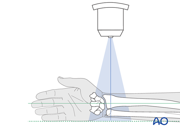
Tangential views
Use additional tangential views to clear the radiocarpal joint space.
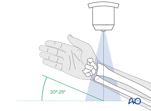
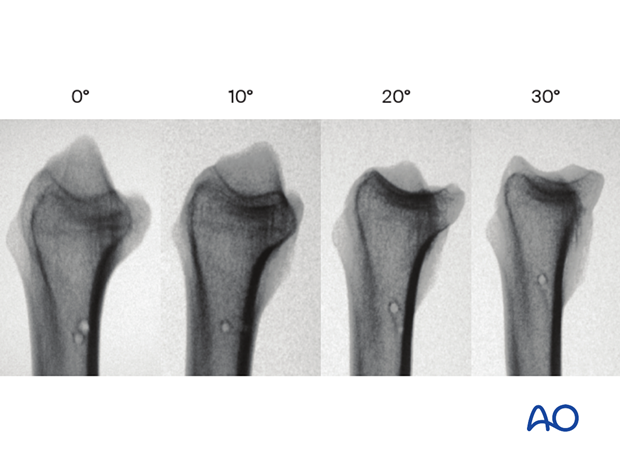
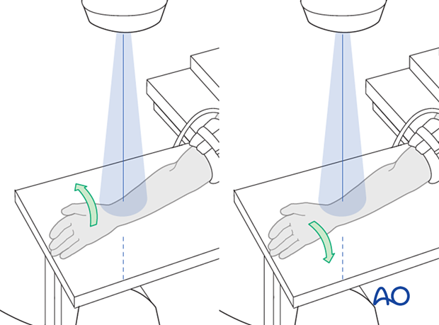
Usually, raise the forearm by about 20°–25° to adjust for the radial inclination.
This series of images shows the representation of the radiocarpal joint surface depending on the angle of the beam.
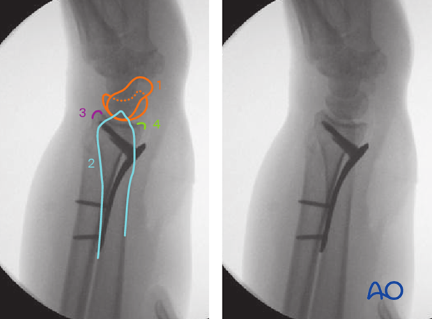
Anatomical lines and landmarks
The following lines and landmarks are seen:
- Lunate and scaphoid
- Distal ulna
- Dorsal rim
- Palmar rim
Verification of optimal view
The optimal view is obtained when the pisiform projects onto the middle/distal third of the scaphoid.
- Scaphoid
- Lunate
- Radial styloid
- Capitate
- Pisiform
- Ulnar head and styloid
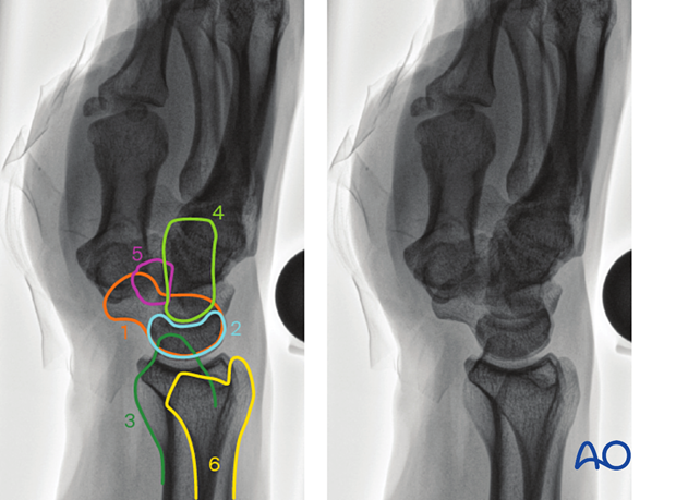
Correct intraoperative lateral view
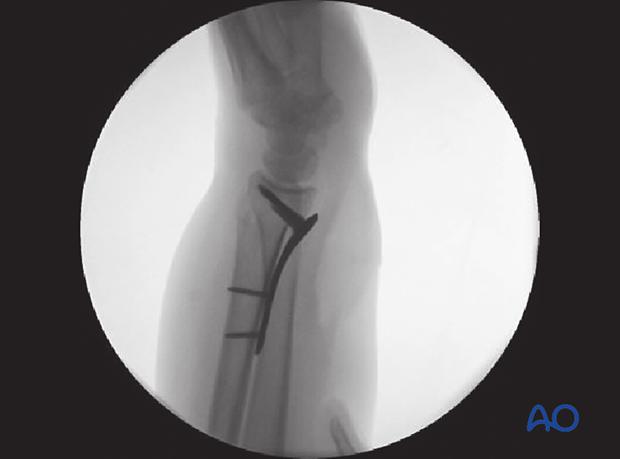
Different intraoperative lateral tangential views
What can be observed
This view is particularly useful for identifying:
- Böhler’s angles
- Radiocarpal joint congruency
- Position of the distal ulna relative to the radius
- Correct plate position
- Correct screw position
4. Oblique views (supination and pronation)
Positioning for optimal view
- With the beam oriented vertically, the hand is pronated supinated about 45° out of the neutral position.
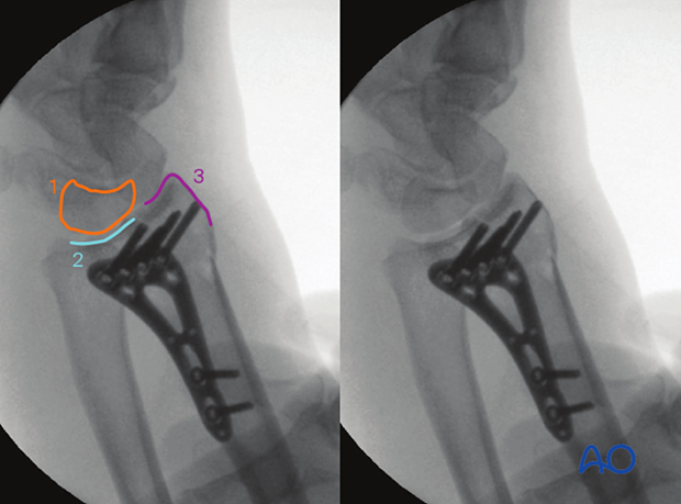
Anatomical landmarks and lines
Dorsoradial or supination viewThe following lines and landmarks can be observed:
- Lunate
- Lunate facet
- Dorsoradial (radial styloid)
The following lines and landmarks can be observed:
- Scaphoid
- Scaphoid facet
- Dorsoulnar (“dorsal corner”)
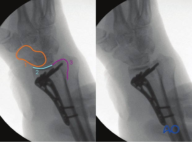
Verification of optimal view
- Dorsoradial view: lunate, lunate facet, and dorsoradial contour of radial styloid visible
- Dorsoulnar view: scaphoid, scaphoid facet, and dorsoulnar contour (“dorsoulnar fragment”, “dorsal corner”) visible
Left: correct intraoperative dorsoradial (supination) view
Right: correct intraoperative dorsoulnar (pronation) view
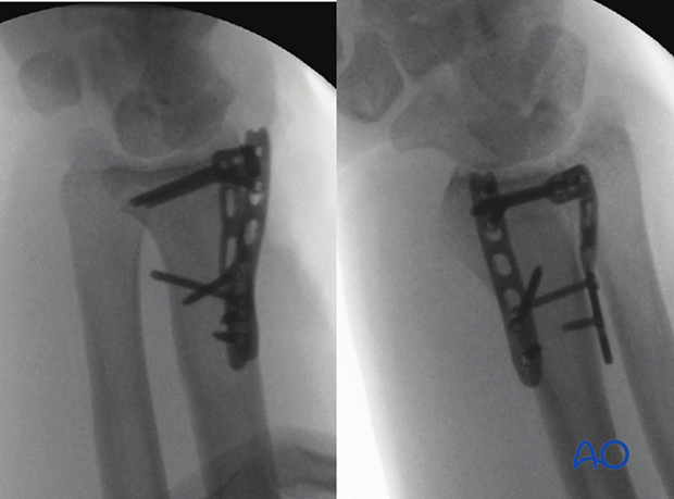
What can be observed
This view is particularly useful for identifying:
- Dorsoradial view: lunate facet, palmar ulnar fragment (“palmar corner”); dorsoradial contour of radial styloid: screw penetration of 2nd compartment
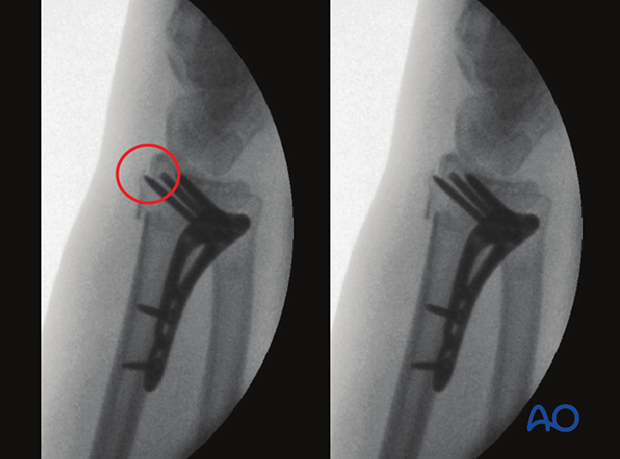
- Dorsoulnar view: scaphoid facet, dorsoulnar fragment (“dorsal corner”); screw penetration of 3rd and 4th compartment
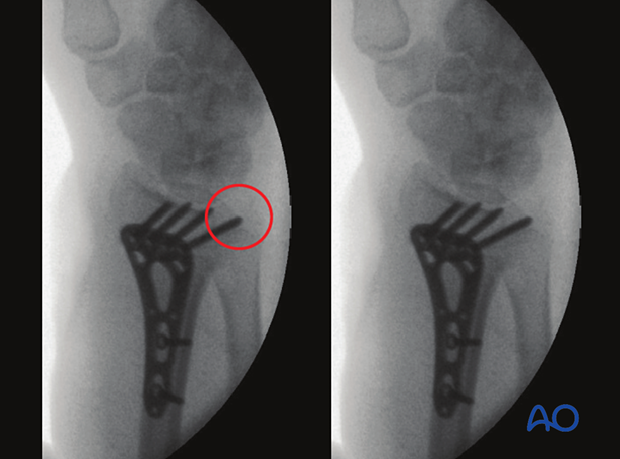
5. Dorsal views (dorsal tangential and skyline views)
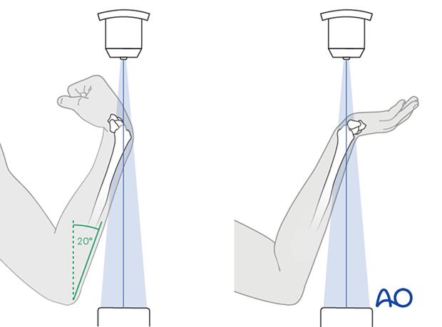
Positioning for optimal view
- The C-arm beam is usually in a vertical position
- Lift the forearm upright at a ca 20° angle to the beam
- Flex the wrist to obtain the dorsal tangential view
- Extend the wrist to obtain the skyline view
Anatomical landmarks and lines
Dorsal tangential viewThe following lines and landmarks can be observed:
- Lunate
- Sigmoid notch
- Scaphoid
- Dorsal rim
- Scapholunate joint space
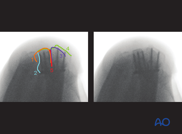
The following lines and landmarks can be observed:
- Palmar rim
- Sigmoid notch
- Radial styloid
- Dorsal rim
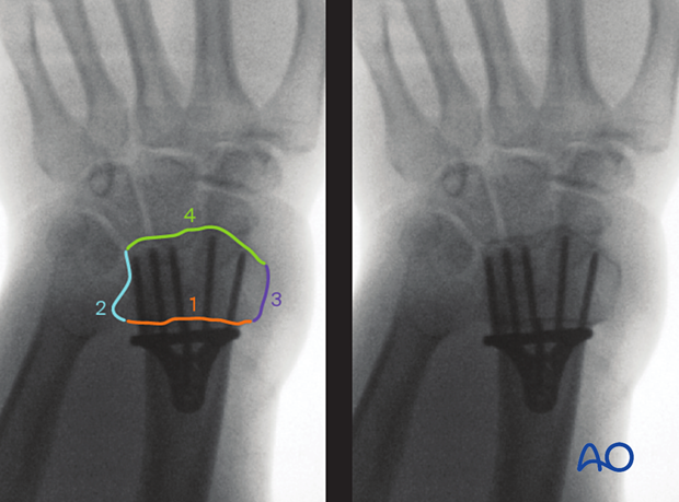
Verification of optimal view
The optimal view is obtained when the following is visible:
- Dorsal rim of the radius
- Sigmoid notch
Correct intraoperative dorsal tangential view
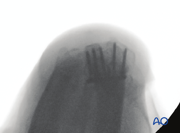
Correct intraoperative skyline view
What can be observed
This view is particularly useful for identifying:
- Screw penetration of dorsal compartments, especially the 3rd
- Screw penetration of sigmoid notch
Intraoperative dorsal tangential view: screw penetration of 3rd compartment
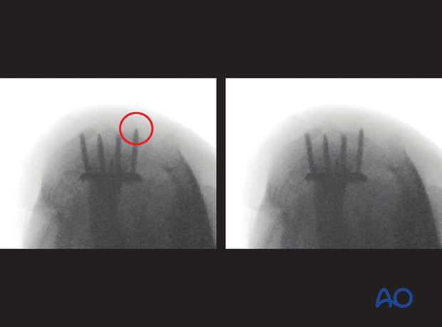
Intraoperative skyline view: screw penetration of 3rd and 2nd compartment
