Virtual planning and intraoperative navigation
1. Introduction
Indications
Whenever an intraoperative CT scanner is available, an intraoperative scan should be obtained for intraoperative evaluation of the reduction.
Severe orbital fractures, especially those that involve more than one wall benefit from virtual planning and intraoperative navigation.
Any orbital fracture benefits from intraoperative CT scanning to visualize adequacy of orbital wall reconstruction.
When using computer assisted surgery, the reduction (and fixation if necessary) is performed according to standard procedures as described in the AO Surgery Reference. It should be considered an adjunct to surgical treatment.
Computer assisted surgery in treating fractures allows virtual preoperative planning of the desired reconstruction using preoperative CT scans and appropriate software.
Intraoperative imaging combined with image fusion of preoperative and intraoperative CT scans, and the virtual plan allows verification of proper reconstruction.
When dealing with complex fractures, intraoperative navigation is extremely useful to assist in properly reconstructing the orbital walls. Often intraoperative correction of orbital wall reconstruction is necessary. Rather than performing repeated intraoperative CT scans, radiation dose-free intraoperative navigation provides intraoperative guidance to the virtually planned reconstruction.
In complex orbital floor fractures radiopaque material for orbital wall reconstruction can easily be visualized by imaging allowing intraoperative or postoperative verification of proper reconstruction.
With this technique, insufficient orbital reconstruction can be can be identified and corrected, eliminating the need for secondary procedures which may be necessary if only postoperative imaging is performed.
Intraoperative imaging requires an additional 10-15 min.
Computer assisted orbital reconstruction planning
Reconstruction of complex orbital wall defects may benefit from preoperative virtual insertion of anatomically preformed orbital implants.
Some complex zygomatico-orbital defects may require patient specific implants for alloplastic reconstruction of orbital walls. This can be performed by transferring virtual preoperative planning into CAD-CAM tools to create patient specific alloplastic implants or by pre-bending standard implants with the use of stereolithographic models either from patients' anatomy or from virtually preplanned reconstruction.
Useful additional reading
2. Virtual planning
Proper preoperative examination of CT-scans require multiplanar views consisting of axial, coronal, sagittal, and 3D-reconstruction.
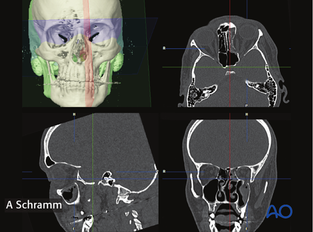
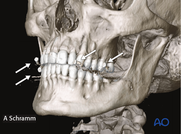
To facilitate intraoperative navigation, fiducial markers on the CT scan have to be included. In a case where the maxilla is not fractured, fiducial markers can be fixed to dental splints. Alternatively, titanium bone screws can be inserted into the skull prior to CT scanning.
Skin fiducials or laser surface scanning in craniofacial trauma are not applicable due to soft tissue changes.
In case shown here, fiducial markers attached to a dental splint were used.
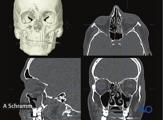
Orientation of the data sets
The first step in preoperative planning is anatomically correct orientation of the data set according to patient's individual anatomy.
Segmentation
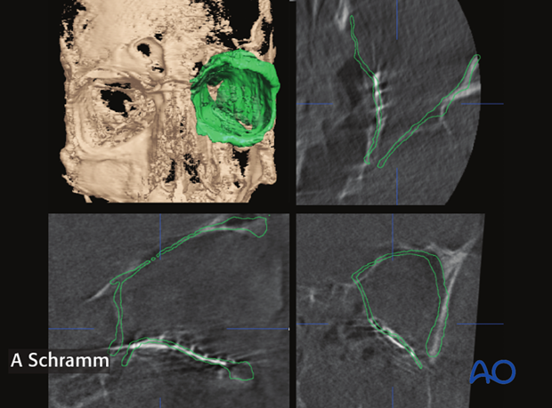
For virtual orbital reconstruction, auto segmentation of the unaffected orbit is performed first and then mirrored to the affected side. 3-dimensional positioning of the mirrored segment allows for anatomically correct virtual orbital reconstruction.
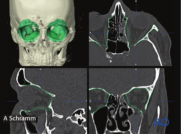
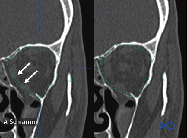
In a case of bilateral trauma, the contours of the auto segmented orbits can be virtually drawn, erased and bent (arrows).
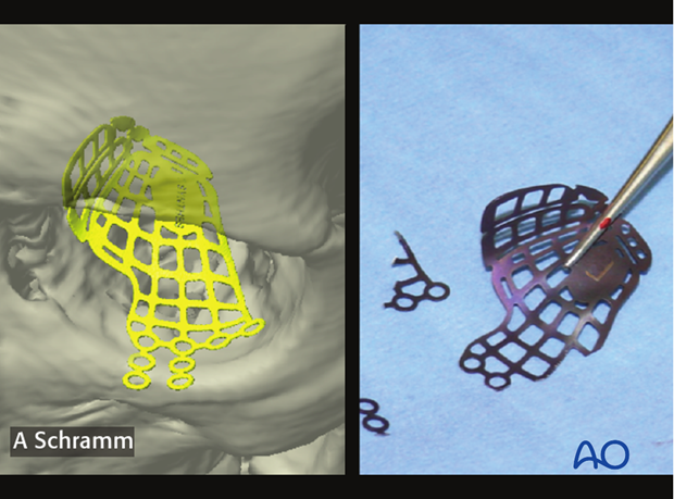
Virtual insertion of anatomically preformed titanium mesh
Anatomically preformed titanium meshes helps achieve anatomically correct reconstruction of medial wall and orbital floor fractures.
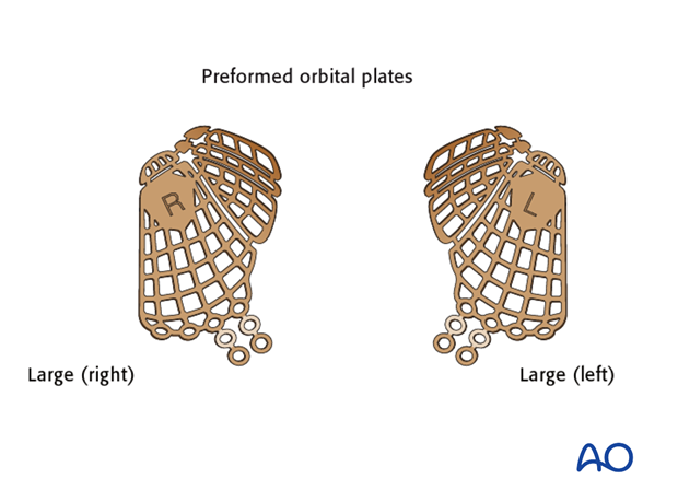
Virtual insertion of the anatomically preformed titanium mesh allows preoperative selection of the correct implant size (large or small). The virtual orbital reconstruction (green line) facilitates correct 3 dimensional positioning of the virtual implant.
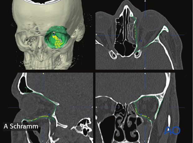
After correct virtual positioning of the anatomically preformed orbital implant, areas to be trimmed are noted for later implant modification in the operating room.
3. Orbital reconstruction using Intraoperative navigation
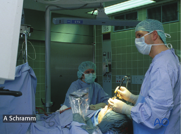
Tracking of patients head is achieved with a dynamic reference frame (DRF) attached to the Mayfield clamp. Alternatively the DRF can be attached to cranial bone. Headsets should be avoided due to soft tissue movement.
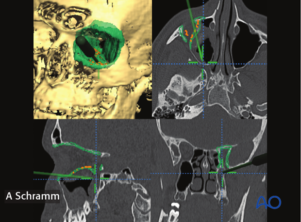
Navigational guidance helps identify the proper anatomic structure, especially in the posterior part.
The screen shot on the left, shows the pointer placed below the posterior ledge of the orbit, indicating a typical dissection mistake in the posterior orbit.
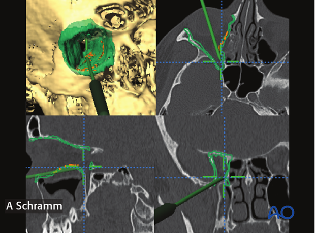
With navigational information, the surgeon can more readily identify the anatomy of the fracture.
The screen shot on the left shows the pointer placed on the posterior shelf of the orbit, indicating the correct position of the posterior end of orbital floor reconstruction.
Control of mesh position using intraoperative navigation
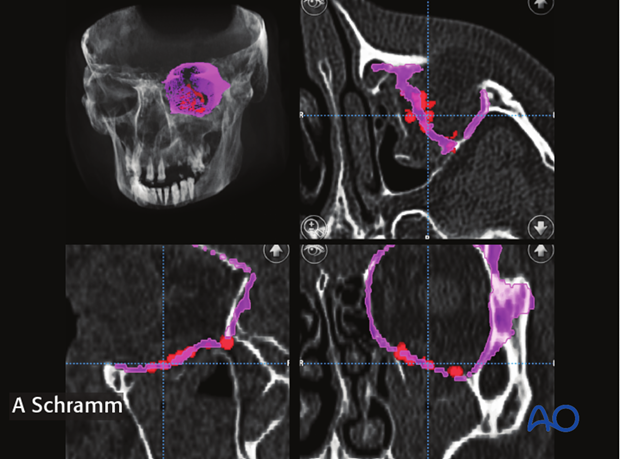
To verify satisfactory orbital wall reconstruction, the navigation pointer is placed on the surface of the orbital implant to correlate its position to the virtual reconstruction. The pointer is moved over the surface of the inserted implant and the different points are collected automatically by the navigation software.
This procedure has to be repeated after any changes of implant position.
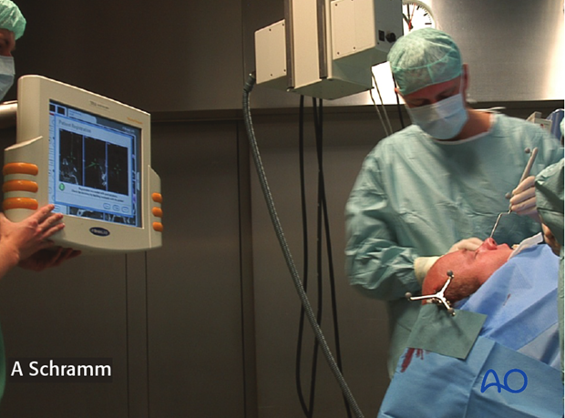
After having detected the surface of the inserted implant, the surgeon can check the position of the implant visualized by red spots against the virtual orbital reconstruction (purple line). If malpositioned, the implant has to be re-adjusted and its new position verified.
4. Intraoperative or postoperative assessment of reconstruction
To verify that the orbit has been properly reconstructed, a CT scan is performed intraoperatively.
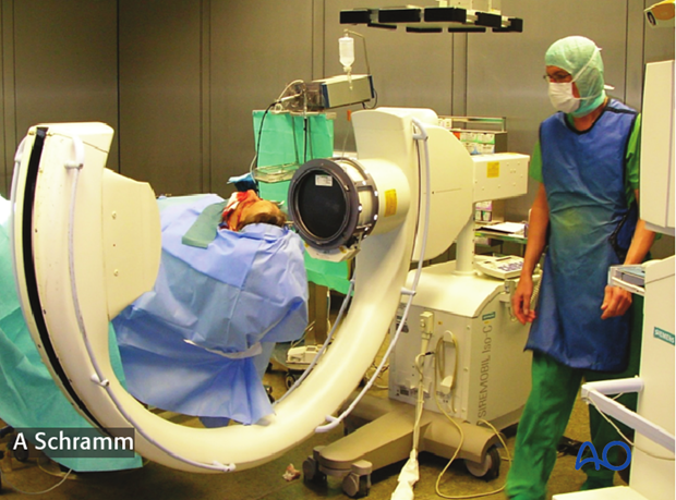
The correct anatomic shape and position of the titanium mesh used for orbital wall reconstruction can be verified in the intraoperative CT scan. Due to smaller radiation volumes used in intraoperative CT-scans the evaluation of symmetry is limited. Bigger scan volumes should be avoided due to higher radiation dose.
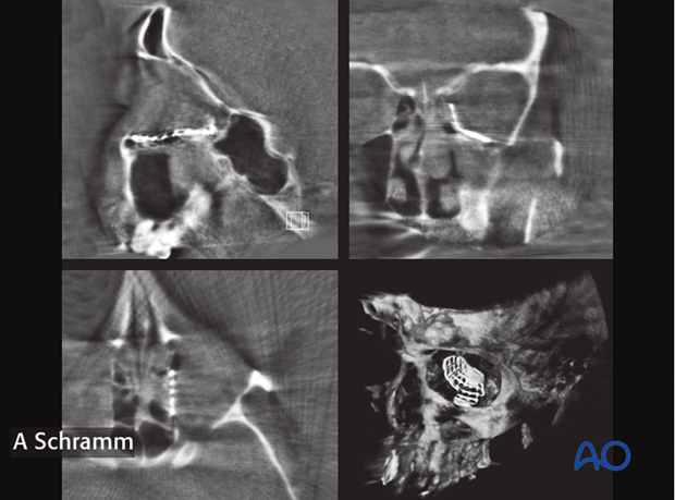
To better verify the reconstruction, the intraoperative CT-scan is automatically fused with the preoperative planning data set. This allows for correlation between shape and positioned of the orbital implants and the ideal virtual orbital reconstruction. The virtual preoperative planning acts as a virtual template.
Note how the orbital implant perfectly fits the virtual plan (green).
This technique can be used for all orbital wall reconstructions with radiopaque material.
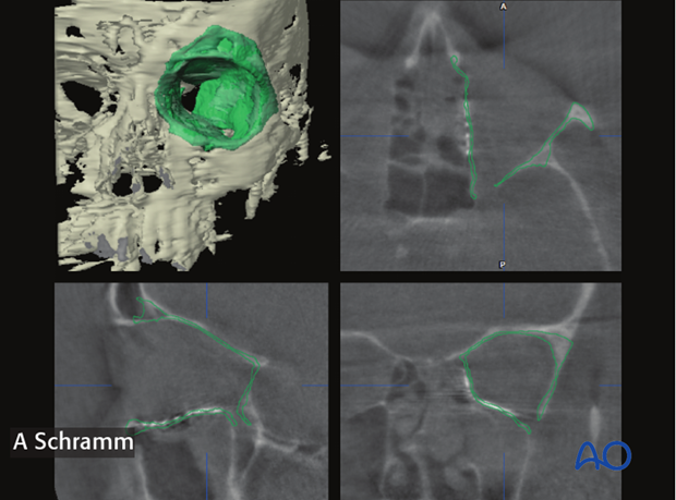
In case the orbital walls have not been properly reconstructed, correction of shape and position of the implant is recommended followed by navigational control or by a second intraoperative CT-scan.
As seen on the left screen shot, positioning of the titanium mesh does not match the contours of the virtual orbital reconstruction (green line). In this case, correction of the position of the implant was performed...
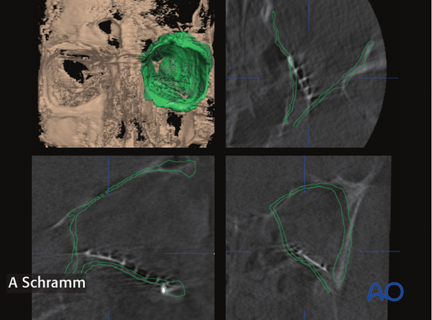
...followed by intraoperative imaging to verify anatomically correct orbital wall reconstruction.
